PID controller
886 words · 5 min read · 2 sources
A PID controller is a feedback algorithm that continuously corrects a robot's behaviour by measuring the gap between where it is and where it should be, then calculating a precise corrective output in real time.
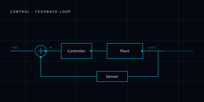
Imagine you're in the shower and the water comes out too cold. You turn the hot tap slightly — but you overshoot and now it's scalding. You turn it back. After a few nervous adjustments you settle on just the right temperature. Without realising it, you were doing what a PID controller does: measuring the gap, correcting, and steadying.
🇮🇳 In India
The self-balancing robots built in IIT robotics clubs use PID to stay upright. Every drone you see in the sky is using PID.
🤯 PID was invented in 1911 for ship autopilots. The same 113-year-old math runs inside your phone's camera stabiliser today.
🎯 Quick challenge
What do P, I and D stand for in PID?
Imagine you're in the shower and the water comes out too cold. You turn the hot tap slightly — but you overshoot and now it's scalding. You turn it back. After a few nervous adjustments you settle on just the right temperature. Without realising it, you were doing what a PID controller does: measuring the gap, correcting, and steadying.
That process — measure, compare, correct — is the heartbeat of almost every controlled machine on the planet.
What PID actually means
PID stands for Proportional–Integral–Derivative. Each word describes one part of the correction calculation.
Proportional (P) reacts to the current error. If the robot's arm is 10 degrees off target, the P term pushes it with a force proportional to that gap. Big gap, big push. Small gap, small push. The problem: the arm might never quite reach the target — there's often a small steady residual error.
Integral (I) adds up all the past errors over time. If the arm has been slightly short for five seconds, the I term notices and adds extra force to cancel out that persistent shortfall. It fixes the long-term residual that P alone leaves behind.
Derivative (D) looks at how fast the error is changing. If the arm is zooming towards the target, D applies a brake to prevent overshoot. It's essentially anticipating the future based on the present rate of change.
Together, the three terms are summed into a single output signal — a motor voltage, a valve opening, a thrust level — that steers the system smoothly to its target.
A real example: drone altitude hold
When a DJI Mavic Mini hovers at 5 metres, a PID controller runs dozens of times per second. The P term pushes the motors up if altitude drops. The I term corrects for persistent wind. The D term damps the oscillation so the drone doesn't bob up and down like a cork. The result feels effortless, but underneath it's a tight control loop running at 100 Hz or faster.
Why it matters in robotics
PID controllers are everywhere: robotic arms, self-balancing robots like Segways, autonomous vehicles maintaining lane position, CNC machines cutting to micrometer precision, temperature controllers inside 3D printers. The algorithm is only three terms, yet it handles an enormous range of real-world problems. Engineers spend considerable effort "tuning" the three gain values — setting P too high causes oscillation, I too high causes slow wobble, D too high amplifies noise.
The math (what's actually computed)
Let the error be e(t) = setpoint − measurement. The control output is:
u(t) = Kp·e(t) + Ki·∫₀ᵗ e(τ) dτ + Kd·de(t)/dt
- Kp (proportional gain) scales the present error.
- Ki (integral gain) scales the accumulated past error — it eliminates the steady-state offset that P alone leaves.
- Kd (derivative gain) scales the rate of change of error — it adds damping and anticipates overshoot.
On a real robot this runs in discrete time at a fixed loop rate dt:
integral += error * dt
derivative = (error - prev_error) / dt
output = Kp*error + Ki*integral + Kd*derivative
prev_error = error
How engineers actually tune it
- Manual / heuristic: raise Kp until the response is fast but starts to oscillate, add Kd to damp the overshoot, then add just enough Ki to remove any remaining steady-state error.
- Ziegler–Nichols: raise Kp (with Ki = Kd = 0) until the loop shows sustained oscillation. Record that ultimate gain
Kuand oscillation periodTu, then setKp = 0.6·Ku,Ki = 1.2·Ku/Tu,Kd = 0.075·Ku·Tu. A fast starting point — usually aggressive, so detune from there. - Model-based / auto-tuning: many industrial controllers estimate a plant model and compute gains (relay auto-tuning, IMC). Great when you have a decent model.
Three things that bite you in practice
- Integral windup. If the actuator saturates (motor already at 100%), the integral keeps accumulating and the system massively overshoots later. Fix: clamp the integral (anti-windup) or stop integrating while saturated.
- Derivative kick. A sudden setpoint change makes
de/dtspike, slamming the actuator. Fix: take the derivative of the measurement, not the error. - Noise amplification. The D term amplifies sensor noise. Fix: low-pass filter the derivative, or drop D and use a PI controller.
When PID isn't enough
PID assumes a roughly linear, single-input/single-output system. For strongly nonlinear, coupled (MIMO), or constraint-heavy systems — a legged robot's balance, a drone's full 6-DOF pose — engineers move to gain scheduling, feedforward + PID, or model-based controllers like LQR and Model Predictive Control (MPC). PID is still often the inner loop underneath them.
Check your understanding
1. Why does a pure P controller often leave a small steady-state error, and which term fixes it? The proportional term produces zero corrective push exactly when the error is zero, so it settles slightly short of target under a constant load; the integral term accumulates that residual and drives it out.
2. Your arm overshoots badly every time it recovers from hitting a limit — what's happening and how do you fix it? Integral windup while the actuator was saturated; add anti-windup (clamp or freeze the integral during saturation).
3. Adding derivative made the motor buzz and jitter — why, and what are two fixes? D amplifies sensor noise; low-pass filter the derivative or reduce/remove Kd.
Despite being invented in the 1930s for ship steering, the PID controller still runs inside almost every servo motor and drone you'll ever touch.
Ask R2 Co-pilot anything you didn't understand about PID controller. It'll explain it plainly.
Tune a PID controller
Drag the sliders to retune the controller. The cyan line is the robot trying to reach the dashed target. What is PID?
Learn this in the Academy
🔌W-03: PID Control in Practice
Hands-on lesson · Wire track
Keep going
3D Gaussian Splatting
3D Gaussian splatting represents a scene as millions of tiny colored blobs, rendering photorealistic 3D in rea…
Concept6D Pose Estimation
6D pose estimation figures out an object's full position and orientation in 3D from a camera — not just where …
ConceptA* (A-Star) Pathfinding
A* finds the shortest path between two points on a grid or graph. It is the most-used pathfinding algorithm in…
Last updated · 2026-05-19
Community discussion
0 questions & insightsLoading discussion…
Spotted something off? Report an error →